TOTAL FREE HEALTH AND SAFETY DOCUMENTS DOWNLOADING SOURCE


Breaking

Wednesday, August 11, 2021

August 11, 2021

Method Statement Damp Dusting of Horizontal and Vertical Surfaces

1. PURPOSE 

The purpose/aim/objective of this Method Statement (MST) for Damp Dusting of Horizontal and Vertical Surfaces and explain in detail the procedure such as;

2. Health and Safety Procedures 

  1. Name of On-Site First-Aiders
  2. First Aid Box Location
  3. Name of Nearest Hospital
  4. Nearest Hospital Contact No
  5. Designated Excavation Location

Health & Safety and Environment

  1. Make sure that colour coding system is followed at all times.
  2. Never mix cleaning agents, as poisonous gases could result-refer to manufacturers’ instructions.
  3. Do not climb on chairs or desks and do NOT practice overreach.
  4. All equipment should be left clean, dry and tidy in the storage area after use.

Equipment, Devices & Machinery

Details

  1. Colour-Coded Bucket
  2. Colour-Coded Cloth
  3. Vileda cloths
  4. Rubber Gloves
  5. General-Purpose Detergents such as Hard Surface Cleaner or similar
  6. Scope of Work: Damp Dusting of Horizontal and Vertical Surfaces

Methodology

  1. Put on rubber gloves.
  2. Prepare the cleaning solution following the manufacturers’ instructions.
  3. Make sure that the bucket is always placed sensibly and does not pose a hazard to others.
  4. Dampen or rinse a cloth in the cleaning solution – wring out the cloth as much as you can so that it is barely damp.
  5. Ensure the surface is left as dry as possible with an even finish (not streaky!).
  6. Change the cleaning solution when it becomes soiled.
  7. Use the selected cleaning solution/substances to remove any grease marks or stubborn stains.
  8. Replace items onto the clean surface.
  9. After use, all equipment and machinery should be inspected, cleaned, dried and returned to the storage area/warehouse/store.
  10. Remove gloves and wash hands.
  11. Remove items from the surface to be cleaned.
  12. To Damp dust flat surfaces (furniture, floors, walls, etc.), wipe in straight lines cleaning the edges first.
  13. Wipe the main surfaces in a figure of eight patterns.
  14. Frequently turn the cloth and rinse in the cleaning solution

Download File
August 11, 2021

Method Statement for Damp Moping/Single Solution Moping

1. PURPOSE 

The purpose/aim/objective of this Method Statement (MST) for Damp Moping/Single Solution Moping and explain in detail the procedure such as;

2. Health and Safety Procedures 

  1. Name of On-Site First-Aiders
  2. First Aid Box Location
  3. Name of Nearest Hospital
  4. Nearest Hospital Contact No
  5. Designated Excavation Location

3. Health & Safety and Environment

  1. Make sure that the colour coding system is adopted at all times.
  2. Never mix cleaning agents, as poisonous gases could result-Refer to manufacturers’ instructions.
  3. Do not climb on chairs or desks and do NOT practice overreach.
  4. All equipment should be left clean, dry and tidy in the storage area after use.

4. Equipment, Devices & Machinery

Details:

  1. Colour-Coded Bucket
  2. Colour-Coded Cloth
  3. Vileda cloths
  4. Rubber Gloves
  5. General-Purpose Detergents such as Hard Surface Cleaner or similar
  6. Scope of Work: Dusting/Single Solution 

5. Methodology

  1. Put on rubber gloves.
  2. Prepare the cleaning solution following the manufacturers’ instructions.
  3. Make sure that the bucket is always placed sensibly and does not pose a hazard to others.
  4. Dampen or rinse a cloth in the cleaning solution – wring out the cloth as much as you can so that it is barely damp.
  5. Ensure the surface is left as dry as possible with an even finish (not streaky!).
  6. Change the cleaning solution when it becomes soiled.
  7. Use the selected cleaning solution/substances to remove any grease marks or stubborn stains.
  8. Replace items onto the clean surface.
  9. After use, all equipment and machinery should be inspected, cleaned, dried and returned to the storage area/warehouse/store.
  10. Remove gloves and wash hands.
  11. Remove items from the surface to be cleaned.
  12. To Damp dust flat surfaces (furniture, floors, walls, etc.), wipe in straight lines cleaning the edges first.
  13. Wipe the main surfaces in a figure of eight patterns.
  14. Frequently turn the cloth and rinse in the cleaning solution

Download File
August 11, 2021

Battery & Battery Charger System Installation Checklist

To prepare checklist for  the Battery & Battery Charger System inspection, following are some main points:

Before Installing or Maintaining Capacitor or Capacitor Banks, Employees must Ensure That They:

Before Installing or Testing DC Systems or Apparatus, Employees must Ensure that they:

  1. Verify CSA Certification Marking (or Equivalent)
  2. Check All Battery Cells for Physical Damage & Leaks.
  3. Check Batteries with Voltmeter for Correct Voltage.
  4. Record And Verify Nameplate Data following Approved Drawings and Specs.
  5. Work Must Be Completed Utilizing Proper PPE & Safe Work Procedures Must Be Followed.

Verification of the Annunciator Installation:

  1. Verify proper installation of battery racks, anchoring, earthquake bases, battery cells & grounding as per code, AFC drawings and manufacturer’s specs.
  2. Verify the battery polarity and compare it to charger polarity.
  3. Check all inter-cell strap connections for ampacity and tightness.
  4. Check the battery terminals for tightness and general appearance.
  5. Check that termination is complete and following approved drawings and manufacturer’s specification & covered with protective base.
  6. Check all conductors are labelled and identified, verify positive and negative conductors.
  7. Check the rating of all dc distribution equipment fuses or breakers following approved drawings and specifications.
  8. Check if battery cabinets or vault room is well ventilated as per applicable codes.
  9. Check for cleanliness and inspect for tools or parts lying in the battery and battery charger cabinet.

Download File

Battery & Battery Charger System Installation Checklist

Tuesday, August 10, 2021

August 10, 2021

METHOD STATEMENT FOR POWER FLUSHING OF EXISTING DOMESTIC CENTRAL HEATING SYSTEMS

METHOD STATEMENT FOR POWER FLUSHING OF EXISTING DOMESTIC CENTRAL HEATING SYSTEMS


To download the Method Statement for power flushing of existing domestic central heating systems , just click in the download link at the end of this article:

Power flushing using the Power Flow Flushing Machine (PFFM). Except for some boiler amendments power, flushing with the Power Flow Flushing Machine (PFFM) should be undertaken after completion of any installation or repair work.


Preliminary Checks

  • Fill the PFFM system, empty all high points, pumps and radiators.
  • Check closely for any possible leaks and repair as required.


System Preparation

  1. Turn off all electrical controls for the plant or area being flushed and make electrically isolation of the system.
  2. Note the setting of each valve before opening them, so that the system can be re-instated after flushing.
  3. Open all radiator valves to their maximum setting and remove TRV (Thermostatic Radiator Valve) heads to ensure maximum flow through the valve.
  4. Set diverter or zone valves to manual.
  5. Anti-Gravity Valves-AGV (non-return valves) if installed should be bridged, bypassed or temporarily removed.


Set-Up and Connection of the Power Flow Flushing Machine (PFFM)

  1. Always employ best practices when protecting customer’s property for wet works.
  2. Connect up the ½" clear mains water inlet hose. ¾" clear dump and overflow hoses and ¾" yellow rubber flow and return hoses to the Power flow by their Cam-lock connectors. Connect the Flush buddy between the flow/return valve and the hose using the Cam-lock connectors provided. The direction of flow for the Flush buddy is not important.
  3. Ensure that the isolating valves on the flow and return hoses, mains fill and dump valve are all in the closed position and that the waste hose and overflow both terminate in a foul drain.
  4. Ensure that the dump hose and overflow hose both drain to a point below the dump valve on the
  5. Power flow flushing unit. Failure to do so will prevent the wastewater from flowing to drain and may result in overflow of the Power flow tank. 
  6. Isolate the circulator pump and, if a PFFM flow Pump Head Adapter is available, remove the pump head and connect the adapter to the in-situ pump body. Alternatively, remove the system circulator and connect the adapter elbows supplied with the Power flow unit across the power flow pump connectors. Make a Coupling to the pump head adapter, or the adapter elbows to the yellow flow/return hoses. For combination boilers where a pump head adapter is not available, connect by fitting the ¾" Power flow/return hoses directly to the main system flow and return or across a radiator. Connecting across a radiator will minimize the flow rate and may affect the efficacy of the power flush.
  7. Isolate the electricity supply to the system circulator, if in doubt, seek the advice of a qualified electrician.
  8. Connect the power lead on the Power flow flushing unit to the electricity supply via an RCD.


Operation of the Power Flow Flushing Machine (PFFM).

  1. Turn on the mains supply and fill the vessel between the maximum and minimum marks.
  2. Open the flow and return valves and allow the unit to run for 15 minutes with all radiator valves open, reversing the flow regularly.
  3. Dump the dirty water to drain whilst adding clean water to the reservoir tank until the TDS of the dump water is within 20% of the incoming mains water.
  4. Refill the system and add the PFFM cleaning product of choice to the Power flow Flushing Unit via the chemical addition port. Open the mains water inlet valve and fill it with water to approximately halfway between the maximum and minimum liquid level markers on the reservoir. Close the mains water inlet valve.
  5. Open the system pump isolating valves and the flow/return isolating valves on the Power flow flushing unit. Ensure that the dump valve on the Power flow remains closed.
  6. Switch on the machine on the power supply to the Power flow flushing unit. As necessary, control the water level in the reservoir via the use of the mains water inlet valve, ensure that the liquid level in the reservoir remains between the minimum and maximum liquid level markers.
  7. Switch on the boiler and allow the central heating system to reach operating temperature.
  8. Allow the unit to run for 40 -50 Minutes, reversing the flow regularly. Highlight and detect any cold spots on radiators, or blockages during this time. If the system has an indirect cylinder, make a diversion for the flow to the cylinder coil and circulate for 10-15 minutes, reversing the flow regularly. Make a diversion to the water back to the heating circuit.
  9. Shut off all the radiator valves except for the radiator furthest from the Power flow flushing unit (PFFU).
  10. Allow the unit to pump through this radiator for a minimum of 10 minutes or until even heat is achieved over the radiator surface. Reverse the flow regularly during this time. Tap the radiator with a rubber hammer may help to dislodge any debris.
  11. Close the flow and return on the radiator and then move to the next radiator. Open the valves and repeat radiator clean. Proceed until all of the radiators have been cleaned. 
  12. Draining the Power Flow Flushing Machine (PFFM).
  13. Switch off the boiler.
  14. If PFFM Cleaner has been used, add the PFFM System Neutralizer via the chemical addition port and circulate for a further five minutes. The system water should be green in colour. If the water is still red, further neutralizers will be required to be added.
  15. Power flushing using the PFFM Power flow above) power flushing with the PFFM Power flow flushing machine should be undertaken after completion of any installation or repair work.


Preliminary Checks

  1. Fill the PFFM system, empty all high points, pumps and radiators.
  2. Check closely for any possible leaks and repair as required.


System Preparation

  1. Make electrical isolation.
  2. Note the setting of each valve before opening them, so that the system can be re-instated after flushing.
  3. Open all radiator valves to their maximum setting and remove TRV (Thermostatic Radiator Valve) heads to ensure maximum flow through the valve.
  4. Set diverter or zone valves to manual.


Operation of the Power Flow Flushing Machine (PFFM)

  1. Turn on the mains supply and fill the vessel between the maximum and minimum marks.
  2. Open the flow and return valves and allow the unit to run for 20 minutes with all radiator valves open, reversing the flow regularly.
  3. Dump the dirty water to drain whilst adding clean water to the reservoir tank until the TDS (Total Dissolved Solids) of the dump water is within 20-25% of the incoming mains water.
  4. Refill the system and add the PFFM cleaning product of choice to the Power flow Flushing Unit via the chemical addition port. Open the mains water inlet valve and fill it with water to approximately halfway between the maximum and minimum liquid level markers on the reservoir. Close the mains water inlet valve.
  5. Open the system pump isolating valves and the flow/return isolating valves on the Power flow flushing unit. Ensure that the dump valve on the Power flow remains closed.
  6. Switch on the machine on the power supply to the Power flow flushing unit.
  7. As necessary, control the water level in the reservoir via the use of the mains water inlet valve, ensure that the liquid level in the reservoir remains between the minimum and maximum liquid level markers.
  8. Switch on the boiler and allow the central heating system to reach operating temperature.
  9. Allow the unit to run for 50 minutes, reversing the flow regularly. Highlight any cold areas/points on radiators, or blockages during this time.
  10. If the system has an indirect cylinder, divert the flow to the cylinder coil and circulate for 15 minutes, reversing the flow regularly. 
  11. Shut off all the radiator valves except for the radiator furthest from the Power Flow Flushing Unit (PFFU).
  12. Allow the unit to pump through this radiator for a minimum of 10 minutes or until even heat is achieved over the radiator surface. Reverse the flow regularly during this time. Tap the radiator with a rubber hammer may help to dislodge any debris.
  13. Close the flow and return on the radiator and then move to the next radiator. Open the valves and repeat radiator clean. Continue until all of the radiators have been completely and properly cleaned. After all the radiators have been flushed completely, open up the valves on all radiators.
  14. Draining the Power Flow Flushing Machine (PFFM)
  15. Switch off the boiler.
  16. If PFFM Cleaners has been used, add the System Neutralizer via the chemical addition port and circulate for a further five minutes. The system water should be of colour. If the water is still red, more neutralizers are required. 
  17. Open the dump valve on the Power flow flushing unit to send the water to the foul drain.
  18. Open the cold-water supply to the unit and regulate to ensure the water level stays above the minimum mark. 
  19. From a convenient supply point, take a sample of the mains water and measure the total dissolved solids by utilizing the Total Dissolved Solids (TDS) meter. Note the reading on the power flushing monitoring sheet.
  20. Flush the system and allow the water to run to waste until it appears clean. Switch or shut off all radiator valves except for the last radiator to be cleaned appropriately, and continue flushing them with the help of the machine until the wastewater appears clean and neat.
  21. Take a sample of the wastewater and measure it with the Total Dissolved Solids (TDS) meter.
  22. Make a clear Comparison with the meter reading from the wastewater with the previous mains water reading. Continue flushing and sampling the wastewater until the reading obtained with the Total Dissolved Solids (TDS) meter is within 10% of the mains water sample.
  23. Note the Total Dissolved Solids (TDS) reading from the radiator on the power flushing monitoring sheet.
  24. When all the radiators have been cleaned, divert all the flow to the indirect cylinder coil (if present) and flush until the Total Dissolved Solids (TDS) of the dump water is within 10% of the mains
  25. Open all of the radiator valves and continue to flush until the wastewater is within 10% of the mains.
  26. Verify that the system has been adequately cleaned and flushed by undertaking the chloride and copper tests within the PFFM Water Test Kit.


Protecting and Re-Commissioning the System

  1. After the system water has been confirmed as being within 10% of the mains, close the mains water supply and switch off the Power flow flushing unit. Close the system circulator isolation valves and disconnect the unit from the heating system. The Flush buddy can be cleaned ready for re-use, by rinsing under flowing water.
  2. The system should be immediately protected by adding the PFFM Protector system. If the engineer chooses to add the PFFM Protector system via the chemical addition port of the Power flow, care must be taken to ensure that the PFFM Protector system is fully dispersed before disconnecting the machine. This will accomplish in 15-20 minutes approximately.
  3. Re-connect the system circulator and restore the electrical supply to it. 
  4. Install the replacement boiler if necessary. 
  5. PFFM Protector system is supplied with a sticker to indicate the date of treatment and the product used. This should be accomplished and put on the boiler casing in a convenient location to allow future engineers to highlight and know the treatment regime utilized.
  6. Verify Protector level is adequate using the PFFM Protector Test Kit within the PFFM Water Test Kit. 
  7. Overdosing of an inhibitor will not have any adverse effects on the heating system. If necessary, add the PFFM Protector system.
  8. Protector level should be checked on an annual basis. This can be undertaken as part of an annual service using either the Protector test reagent within the Water Test kit or using the laboratory postal service.
  9. The valve on the Power flow flushing unit sends the water to the foul drain.


Download File

Method Statement-power flushing of existing domestic central heating systems

August 10, 2021

Risk Assessment-Removal and Cleaning of Bird, Animal Urine, fouling, Feces, Nest and Guano

To download the Risk Assessment-Removal and Cleaning of Bird,  Animal Urine, fouling, Feces, Nest and Guano, just click in the download link at the end of this article:

1. Hazard

  1. Orthosis
  2. Psittacosis
  3. Campylobacter
  4. Salmonella
  5. Enterica
  6. Extrinsic Allergic
  7. Alveolitis
  8. Site conditions
  9. Dust
  10. Loose slates
  11. Falling Objects
  12. Hazard Details
  13. Contact with
  14. bird guano and
  15. debris through
  16. inhalation,
  17. ingestion,
  18. skin contact.
  19. slips, trips & falls
  20. Breathing in pathogens
  21. from the pigeon’s droppings and dust
  22. Loose slates on the apex or culmination of the rooftop.
  23. Falling objects such as waste materials falling off the top of the steps and injuring somebody

2. Who Can Be Harmed & How?

  • Cleaning/Pest control Technicians, Staff, clients and public

3. Control Measures

  • Educate people about hazards and the need to observe good hygiene.
  • Untreated guano is categorized as hazardous waste/contaminated substances.
  • Removal of nests and debris by professional down and neutralize debris and guano with a disinfectant re-classifying waste and avoiding particles from becoming airborne.
  • Bag and dispose of waste through the licensed carrier.
  • Remove resident birds through trapping, shooting or falconry ensuring compliance with Wildlife and Countryside Act.
  • Net, spike and proof areas to prevent perching.
  • Review regularly
  • Cleaning/Pest control technician to pay special attention to stone steps and take care when using them.
  • Cleaning/Pest control technician to wear suitable non-slip footwear.
  • Cleaning/Pest control technician to use the handrail.
  • Cleaning/Pest control technician to use a face mask at all times, coverall and gloves while working.
  • Disinfect the area before starting work and on completion of work.
  • Cleaning/Pest control technician to try not to work under that area and be careful when doing so.
  • Have somebody appointed and designated as a banksman while working in that area.
  • Cone off an area around the step so that other workmen cannot stray into that area.

For more quality documents downloading click on the 
following link👇

Download File
August 10, 2021

Health and Safety Plan for ELV System

To download the Health and Safety Plan for ELV System , just click in the download link at the end of this article:

Site safety control shall be conducted following the guidelines stipulated in the attached Risk Assessment.

  • To make sure that the Permit to Work System (PTW) should be adopted as per the HSE Plan.
  • To make sure that the lifting operation should be conducted as per the HSE Plan.
  • The copies of Third- party certificate, drivers or operator’s license, vehicle’s registration, and security clearance token to be submitted to organization/company’s safety department before starting the work.

Personal Protective PPE Requirements

PPE is the last line or option of defence and safeguard you and your co-workers, not the first. However, every individual, owner, employer or contractor should provide appropriate PPE to protect the workforce wherever possible. As a minimum for all personal during the works will be a:

  • Hard Hat/Helmet 
  • Safety boots,
  • Coveralls, 
  • Goggles
  • Masks.
  • Harness
  • gloves, etc.

All such required PPE’s will be provided and used at all times. The extra  and  task-specific Personal Protective Equipment (PPE) will be provided and worn according to the risk assessments/JHA.

Emergency Response

  • The Emergency Response  (ER) shall be instituted by Authorized Person. The Emergency Response  (ER) section in the health safety and environmental plan shall be adopted and practised.
  • In case of an Emergency Situation, the following actions shall be activated immediately:
  • Stop the activity
  • Call the emergency number for help
  • Provide first aid and call the ambulance
  • Alert site clinic / Nurse/ First aider


Download File
Health and Safety Plan for ELV System

August 10, 2021

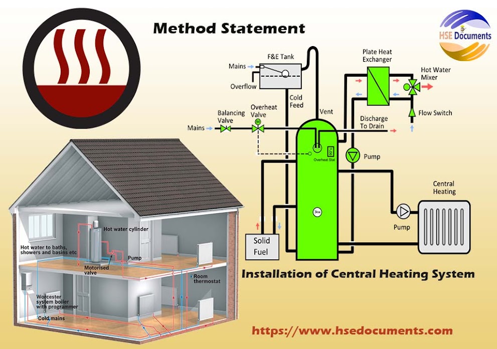
Method Statement for Installation of Central Heating System

To download the method statement Installation of Central Heating System, just click in the download link at the end of this article:

1. Plant/Equipment:

  1. Battery-powered drills saw, and screwdrivers
  2. hand tools
  3. pipe benders
  4. Torch
  5. Blow lamps for soldering
  6. Full PPE

2. Work Method:

  1. On arrival at the client’s home, we would be discussing in detail what works will be carried out and, in the order, they will be carried out.
  2. Lease with the customer to confirm and finalize working hours, the final position of radiators, discuss isolation procedures & strategies of the existing gas and electrical services/installations, and inform the homeowner/client/contractor of the possible potential hazards.
  3. Floorboards lifted where required locating drain points, attaching hose pipes and discharge into the suitable drain.
  4. Isolate water supplies to the existing system.
  5. Use the dust and anti-scratch plastic sheets and other appropriate protection system, remove unnecessary/waste materials such as radiators, old pipes.
  6. Lift carpets if required, floorboards etc. and install new pipework, floor joists noticed or drilled to take the new pipe.
  7. Start and run the new pipework installation, soldering where necessary (make sure that suitable fire extinguisher in place and that no flammable material/substances near soldering points).
  8. Make a connection to all new pipe’s installation to radiators and valves.
  9. Install new boiler along with flue as needed (care and attention when determining the location of the boiler and flue.) Connect the flue pipe and seal with plaster/sand and cement mix.
  10. Make a connection to all new pipe’s installation from the radiators to the boiler. Reconnect the hot & cold services.
  11. Isolate gas pipework from the meter after carrying out soundness test, run and connect ti1enew gas supply as per Required standards and regulations and connect the supply to the new boiler.
  12. Carry out soundness test and purge gas from the meter, ensuring full ventilation.
  13. Connect the boiler and Its controls to the electrical supply ensuring that all eclectics are isolated and fully tested
  14. Pressure the new system and carry out tests for pressure drop, fill system and fully rest hot cold and radiator circuits.
  15. Commission the boiler to manufactures instructions and accomplish the proper and essential paperwork installation.
  16. Hear test the system, test all controls and valves/timers etc.
  17. Make good any walls, doors, ceilings disturbed during installation work.
  18. Final stags: ·
  19. After the new system has been tested to be fully operational, the system will be drained and refilled, flushed with cleaner refilled and the mh1bilor added
  20. The system and Its controls will then be demonstrated to the homeowner ensuring that they are aware of the gas, water, and electrical isolation points.
  21. The sire will be Cleaned of any debris.

Download File

Sunday, August 8, 2021

August 08, 2021

Method Statement-Cleaning Bird and Animal Urine, Feces and Nesting

1. Purpose 

The purpose of this Work Method Statement for the cleaning and removal of birds and animal droppings, urine, nesting (including feathers that may be left behind) and roosting sites can host many diseases. This activity should be performed with strict compliance and implementation of Safety requirements & procedures and project specifications to complete the work for the cleaning and removal of birds and animal droppings, urine, nesting.

2. Scope of Work

The scope of this Method Statement covers the works in this project for the cleaning and removal of birds and animal droppings, urine, nesting.

3. Procedure Procedures for Cleaning

  • Before starting clean-up/cleaning and removal of birds and animal droppings, urine, nesting, the space, ventilate or make airy of the space by opening the doors and windows for at least 20-30 minutes to allow fresh air to enter the area. For cross ventilation, use an exhaust fan or if it is easy and possible. Leave the cleaning area immediately until the airing out period is accomplished.
  • After the venting is accomplished if there is a possibility to contaminate the ventilation inlets or outlets in the space during the cleaning, seal these inlets and outlets before cleaning starts.
  • Wear disposable gloves (e.g., rubber, latex, vinyl), disposable coveralls with head covering, disposable boot covers or rubber boots, a half-face respirator with HEPA (high-efficiency particulate air) filters and eye goggles.
  • Apply proper spray coating and or shower on the animal/birds’ droppings or contaminated materials until it is moist with a bleach solution @ the ratio of 1:10 (1 part bleach, 10 parts water). Allow and wait this disinfecting solution to dry up in for 5-10 minutes.
  • Remove droppings or place contaminated materials into a plastic bag. Use a scrubbing brush or scraper as required and if essential.
  • Double bag waste materials.
  • Do not dry sweep or use compressed air to clean birds and animal droppings, nest or other contaminates.
  • Depending on the level of contamination, it may be desirable to HEPA (High Efficiency Particulate Air) vacuum the surface before applying disinfectant in the next stage.
  • Sterilize or sanitize the surface again using the bleach solution. Completely clean any re-usable Personal Protective Equipment (PPE), tools and equipment with the bleach solution.
  • Once you have removed and cleaned the gloves, wash your hands thoroughly with soap and water.
  • When using or mixing chemicals, ensure that the Safety Data Sheet (SDS) is available. Review manufacturer information on the label or SDS before handling.

4. Equipment 

Equipment likely to be used:

Wire Brushes, scrapers, brushes rags, rubble sacks, tie wraps and relevant PPE.

To  complete  download in d=Word soft copy, click on the following: 👇

Downlead File

Method Statement-Cleaning Bird and Animal Urine, Feces and Nesting

Wednesday, August 4, 2021

August 04, 2021

Gulf car/Club Cart/buggy Driving Safety Instructions

1- Rules of the Road

  • Be a legal age and fully trained to drive a gulf car.
  • Always drive on assigned, designated & approved marked roadside lanes and areas.
  • Always obey all implemented local traffic laws, signs and signals.
  • Yield to Automobiles.
  • Come to full Stop at stop Signs.
  • Follow the Road signs as per{facility/project}.

2-Safety Tips

  • Keep arms and legs inside the gulf car/Club Cart/buggy.
  • Secure your equipment, material or substances while driving the gulf car/club cart/buggy.
  • Enter traffic lane safely before turning left while driving the gulf car/club cart/buggy
  • Be aware of vehicles turning right.
  • Maintain gulf car/club cart/buggy according to the manufacturer’s recommendations.
  • Do not use mobile while driving any of the vehicle/club car, etc.
  • Limit passing slower gulf cars.
  • Pull off the path when you need to stop the gulf car/club cart/buggy.

3- Before You Drive

  • Make sure horn, brakes, and lights work properly before driving the gulf car/club cart/buggy.
  • While driving the gulf car/club cart/buggy, always check, tire pressure, and applicable gauges, and battery charging Status.
  • Before backing up/reversing the gulf car/club cart/buggy, look behind and see that all is clear.
  • If you have any the gulf car/club cart/buggy maintenance issue, please contact the transport department’s maintenance manager/HSE Personnel immediately and don’t operate the club/buggy car.
Download File

August 04, 2021

Near-Miss Report Form-HSE Documents

Following is the format for" Near Miss Report Form". to download the editable Word file, click on the end of this article:

During our daily work or activities (in any field of life), a near-miss may occur at any time. If we want to know what is a "Near Miss?", simply a potential hazard or incident that has not resulted in any human physical/personal injury or property and or asset damage/deterioration.

Examples of Near Miss

Some Examples of Near-Misses are:

  1. Unsafe conditions.
  2. Improper use of equipment.
  3. Use of faulty equipment.
  4. Not following proper procedures, etc.   
  5. How to Avoid Near Misses?

To protect ourselves and our colleagues, it is everyone’s responsibility to report and make rectification or correct any possible and potential hazards as soon as possible. if you are a project health and safety personal or supervisor, please use this Near Miss format to report near-misses at your workplace and make your working environment free from any critical or severe accidents. To report any near miss even minor occurrence always help towards the provision of a safe system of work and it will also make you secure and safe from any legal action and at the same time the fulfilment of your moral obligations.

Near-Miss Report Form-HSE Documents

Download File
Near-Miss Report Form 

August 04, 2021

Method Statement for Screeding Work

1- PURPOSE

The purpose/aim/objective of this Method Statement (MST) for Mortar Screed Works is to highlight and explain in detail the procedure such as;

  1. Design mix, 
  2. Mixing, 
  3. Pouring 
  4. Curing. 

Moreover, to Inform all concerned project engineer and supervisors including workers the value and importance of this activity before implementation. This screeding activity should be executing with rigorous compliance and implementation of Safety requirements, procedure and project specifications to accomplish the work for concrete screed.

2- SCOPE OF WORKS

The scope of Screeding Work Method Statement is to covers the works in (Name of the Building/Project) 

3- PROCEDURE

General

  • All method statements related documents and mix proportion must be approved from concerned department/authority/personal and easily available upon request.
  • Free water shall be removed from the subfloor.
  • Screed shall be laid with a minimum of 50 mm thick.
  • Check that the Mechanical and Electrical services under screed have been completed and protected as per the drawing/specification.
  • The curing arrangement shall be done as per the requirements.
  • Ensure waterproofing as per the approved method and materials only.

To download the complete file for Screeding Work, click on the following link:👇


Download File
Method Statement for Screeding Work.

August 04, 2021

Floor Screeding Inspection Checklist

To prepare checklist for the Floor Screeding inspection, following are some main points:

1- Substrate Surface Preparation

  • The substrate is clean from grease, oil and dirt
  • The substrate is free from cracks and exposed bars
  • Waterproofing is done and completely cured

2- Setting Out / Marking

  • Level pegs provided/available as per the survey marking.
  • Vertical & horizontal control/check was implemented to check all pegs.
  • Appropriate and essential number of level pegs, interval provided at every meter
  • Correct finishing elevation, offset and drop
  • If screeding thickness >25 millimeters, double-check and verify the specification for the requirement of wire mesh/any other reinforcement 

3- Coordination With Other Works

  • Wall plastering within the area completed
  • Concealed services/fittings are laid/installed

4- Mixing & Batching Mortar Screed

  • Clean sand used for mortar screed mixing
  • The material used as per specification
  • The correct mixing ratio of cement to sand, 1:

5- Screeding & Finishing

  • Accomplish level, alignment and evenness are acceptable.
  • Check the falls


Download File
Floor Screeding Inspection Checklist 

Monday, August 2, 2021

August 02, 2021

Fit-Out & Construction Project-Security-Plan

1- Scope of Work  

For the Project, this Security plan applies to all [Organization/Company Name] activities including personnel, Vendors and Subcontractors associated with this Construction/Fit-Out project (s). This Plan addresses all types of security risks and mitigation measures during all phases of this Fit-Out project (s). This Project Security Management Plan will be reviewed from time to time/periodically as the project advances and if any particular site security requirements are identified, shall be agreed upon and implemented/accomplished.

2- Security Objectives for The Construction/fit-out Project

According to the Health, Safety and Environmental (HSE), Quality and Security (Q &S) policy the following main objectives are highlighted for the establishment of a positive and effective approach to safeguard the Project assets from security hazards and threats:

  1. To accomplish the construction/fit-out etc. project without sustaining loss to substance, appliances, materials, equipment, devices and human life.
  2. To enhance the security system by employing highly competent and authorised security specialists.
  3. To develop effective access/egress controls for the prevention of unauthorized persons, visitors or vehicles from entering site/ accommodation, construction, fit-out and pre-commissioning locations.
  4. To develop staff/employee's security protection against aggressors and disincentive/deterrents.
  5. To make sure all vehicle travel is operated and covered under journey management strategy.
  6. To establish an effective working relationship and cooperation with the OWN OWNER and government security personnel.
  7. To make sure an effective Security Operational Control (SOC) by ensuring continual and non-stop communication and intelligence network for threat detection and immediate notification

3- Specific Security Targets

  1. Based upon the above-described goals/objectives fit-out/construction project Security targets have been set.
  2. Zero loss to substance, materials, equipment, appliance and human life.
  3. 100% fencing around the temporary barriers around the work area.
  4. 100% training coverage to all workers/employees/technical staff through Security induction & Orientations.
  5. Maintain 100% record of employees/workers/material & substances /vehicles leaving and entering the Check posts of the site.
To download complete Fit-Out & Construction Project-Security-Plan, Please click on the following download link:

Download File

Sunday, August 1, 2021

August 01, 2021

Skid Steer Loader Inspection Checklist

To prepare checklist for the Skid Steer Loader inspection, following are some main points:

  1. The machine should be physically good & should have a valid TPI Certificate.
  2. No damage to the tire (Bolts, crack, cuts & air pressure, etc.).
  3. Head & tall light and Indicators are in working condition.
  4. The side mirror should be in good condition.
  5. Windshield/glass shield be in proper condition.
  6. The wiper should be in running condition.
  7. Operator cabin should be made by good & sound quality of the material.
  8. Hydraulic cylinders should be in good condition and free from leakage.
  9. Footsteps should be free of slip and trip hazards.
  10. Red triangle/reflective tape should be fixed in front of the vehicle.
  11. Front & reverse horn.
  12. Fire extinguisher in operator cabin.
  13. Operators have a suitable license.

Download File

Skid Steer Loader Inspection Checklist

August 01, 2021

Excavation & Trench Entry Checklist

To prepare checklist for the Excavation & Trench Entry  inspection, following are some main points:


1. Have all legally required permits to work been accomplished and posted?
2. Do Confined Space Entry requirements apply?
3. Has the soil type been determined per occupational health and safety regulation? 
4. Have proper and essential sloping requirements been determined for safe excavation as per occupational health and safety regulation regulations?
5. What type of worker protection will be in place for workers at entry and egress points?
·      Appropriate sloping as required
·      Shoring
·      Trench Box
·      Other
6. Are ladders:
·       Properly deployed at entry/egress points?
·      Tied off at the top
·      Extend above/over shoring or box by 1metre/3ft
·      Within 8m/26ft of where personnel are working
7. Is the worker entry/egress area clear and free of debris?
8. Will the employee/worker/technician be within the "Control Zone" area at any time (other than entry/egress)?
The “Control Zone " is termed as a lateral distance inside the excavation extending
0.5 x D from the top for firmer soils (1.5 x D for fewer firm soils) of the excavation.  (D = depth of excavation) Provides the same level of protection as at the entry/egress point above
9. If the answer to No.7 is “yes”, what type of worker protection will be used for workers in this Control Zone?
10. If shoring is used, has it been designed by a Professional Engineer, and is a design available on site?
11. Is the shoring system inspected daily (as a minimum)?
12. Is excavation spoil kept > 1 meter from the edge of excavation?
13. Are rescue procedures complete and on-site?
14. Are all workers familiar with rescue procedures?
15. Is a watch person required?
Download File

August 01, 2021

Fire Safety Management (FSM) and Fire Emergency Plan (FEP)

The following Fire Safety Management and Fire Emergency Plan is an example for you to prepare your own organization and or company's FSM &FEP document as per your requirements. for the complete document downloading, just click on the link given at the end of this post:

Fire is a common hazard in any part of the Facility or building’s premises. Its ramification and consequences include the threat to human lives, damage to or loss of property, equipment, costly devices and appliances and severe interruption to general business work tasks or available opportunities. 

Management of the risk of fire needs fires safety measures to consist of a combination of essential and proper prevention and protection measures depending upon the facility’s use and or building’s occupancy, the deep-rooted fire risks and the legal obligations, requirements and implications laid on [company/organization] as the employer, occupier/owner or ‘accountable person’. 

The current fire safety management and fire emergency plan apply to all facility/building (such as commercial, offices, shopping malls, workshops, hospitals, educational institutions) premises/areas which are to any extent under the control of the [company/organization] as the employer, owner or main occupier. Its provisions/needs extend to all persons at those facilities/building’s premises including staff of all levels, visitors and main/sub-contractors whether permanently or temporarily involved. 

Where Facility or building’s premises are jointly occupied or share control of Facility or building’s premises with other employers/occupiers then the arrangements for fire safety and maintenance will be coordinated, communicated and documented. In such Facility or building’s areas, the fire & safety arrangements, preparations, procedures and strategies of the main or host tenants shall apply or local variations agreed by all relevant parties and relevant persons. 

The under-discussion fire and safety management and emergency plan apply to all other staff working on the Facility or building’s premises employed by any other employer. In this situation, other staff will comply with these relevant fire safeties polices and requirements of the [company/organization].   

Download File

Fire Safety Management and Fire Emergency Plan